CIVIL WORKS GUIDELINES FOR MICRO-HYDROPOWER IN NEPAL
71
Storage capacity
The basin should be able to store the settled particles for some
time unless it is designed for continuous flushing. Continuous
flushing mechanisms are however not incorporated in micro-
hydro schemes due to the complexity of the design and the
scarcity of water during the low flow season. Hence, the storage
capacity must be sufficiently large that the basin does not
require frequent flushing.
Flushing capacity
The basin should be able to be operated so as to remove the
stored particles from it. This is done by opening gates or valves
and flushing the sediment along with the incoming flow in the
basin. The bed gradient must be steep enough to create velocities
capable of removing all the sediment during flushing.
5.3.2 THE IDEAL SETTLING BASIN
The theory behind the design of a settling basin is derived on
the basis of an ideal basin. Therefore, before proceeding to
the design phase, the concept of the ideal basin needs to be
under-stood. Such an ideal basin is shown in Figure 5.1.
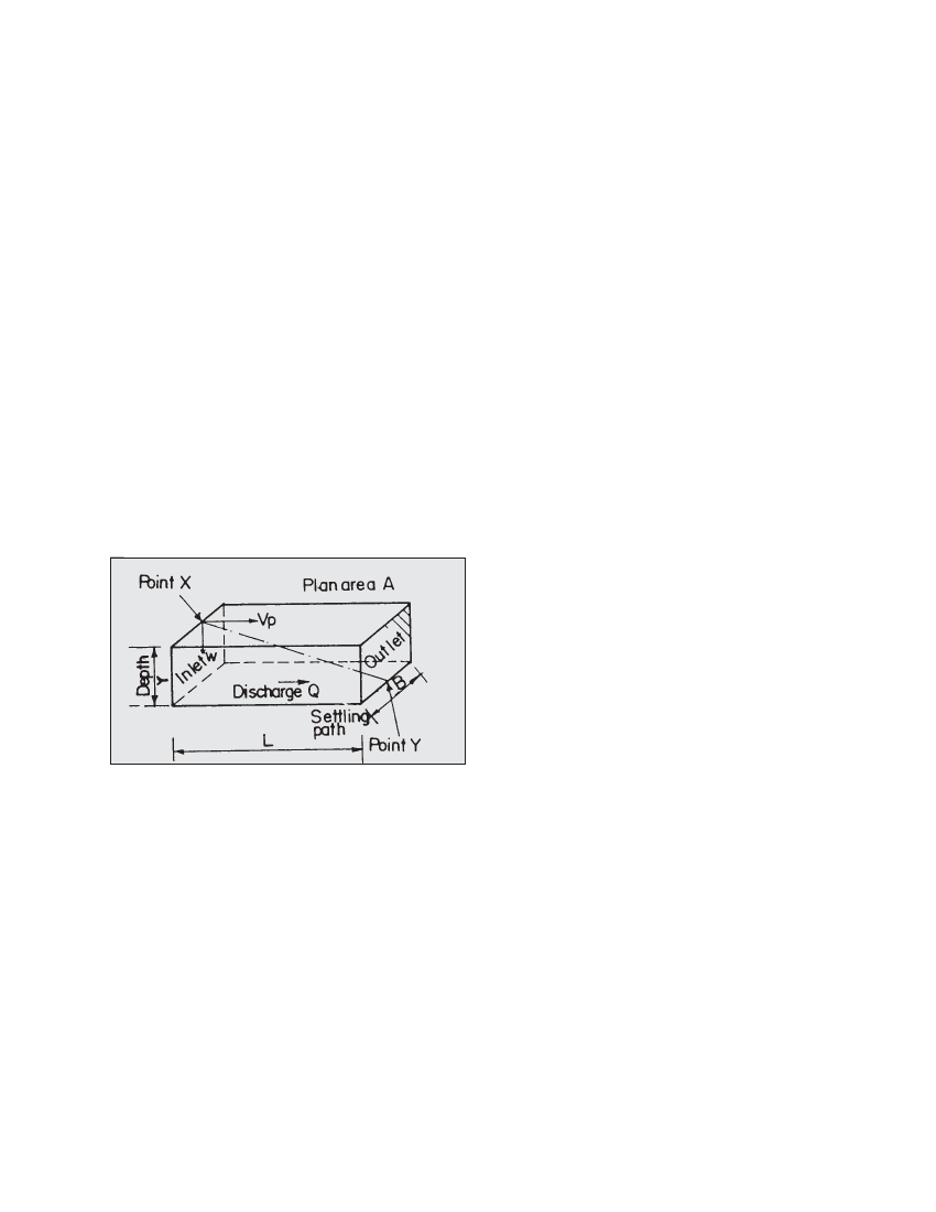
Consider a particle entering the “ideal settling basin” on the
water surface at point X (i.e. beginning of the settling zone)
as shown in Figure 5.1. In this figure:
Figure 5.1 An ideal settling basin
L = length of the settling zone (m)
B = width of the settling zone (m)
Y = mean water depth in the settling zone (m),
aslo called hydraulic depth
t = time for particle to travel the length L (s)
Vp = horizontal velocity component of the particle
(m/s)
W = vertical velocity component of the particle
(ms), i.e., “fall velocity” which is discussed
later
Q = discharge (m3/s)
Then the following equations must hold for the particle to
reach the end of the settling basin (point Y):
y = w t (a)
L = vpt (b)
Q = Bvpy(c)
Substituting for y, vpand t from (a) and (b) into (c) results in:
Q = BLw
Therefore, for a given discharge Q, the plan area of the settling
basin can theoretically be determined for sedimentation of a
particle with fall velocity w. However, in practice, a larger
basin area is required because of the following factors:
the turbulence of the water in the basin;
imperfect flow distribution at the entrance; and
the need to converge (sometimes curve) the flow towards
the exit. Therefore in “real basins” the through velocity is
limited, to reduce turbulence, and the required plan area is
about twice the area calculated for the “ideal basin”.
5.3.3 FALL VELOCITY OF SEDIMENT AND PARTICLE SIZE
The fall velocity, w, characterises the ability of particles of
various sizes to settle out under gravity. For a discrete particle,
this value depends on its size, density, and shape, as well as
the temperature of water.
Figure 5.2 shows the fall velocity in water, w, as a function of
the particle diameter for reference quartz spheres. This figure
can be used to estimate w for the calculations required in the
design of the basin. Note that the temperature effect becomes
less for larger diameter particles.
In micro-hydropower schemes, the settling basin is designed
to trap 100% of particles greater than a certain size,
dlimit Only a proportion of smaller particles will be trapped, but
dlimit is set so that the smaller particles passing though the
basin will not cause significant abrasion damage to the turbine.
For micro-hydro schemes the following procedure is
recommended for the selection of dlimit :
Low head schemes, h≤10 m: dlimit = 0.2 mm to 0.5 mm
Medium head schemes, 10 m < h≤100 m : dlimit = 0.2 to
0.3 mm
High head schemes, h > 100 m : dlimit = 0.1 to 0.2 mm
where h is the gross head.
The current practice in Nepal is to use dlimit of 0.3 mm regardless of
the head of the scheme, which is somewhat arbitrary. The approach
outlined in this section is more logical. This is because for a given
particle size, the higher the head, the more the damage is to the
turbine.
The dlimit range given above as a function of head and flow allows the
designer some flexibility in deciding the particle size to be settled.
The following factors should be used while deciding on the
value of dlimit:
If most particles are highly abrasive (quartz sand or minerals),
then the lower limiting values should be used. If the particles
are softer less abrasive substances, then the higher limiting
values may be acceptable.
Crossflow turbines are relatively less sensitive to soft
impurities such as silt and clays. Other types such as the
Francis turbines are more sensitive to any kind of suspended
matter. Pelton turbines are intermediate.